
A final setup tells you where the teeth end up. It doesn’t tell you where the roots are, how the teeth get there, or what the bite does along the way. Eon Access 2.0 adds tools for those questions. Here is what’s new or updated and why it matters when you are reviewing a case.
1. See the Roots in their Anatomical Context
CBCT integration
- Crown-only planning has a blind spot. Two crowns can look perfectly aligned while the roots underneath are converging, tipping toward each other, or heading for a thin area of bone. With CBCT integration, you can view the actual root positions alongside the surrounding anatomy, directly in the plan you are already reviewing (1).
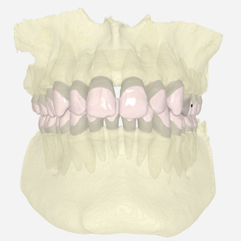
This is useful in a few specific situations:
- Root Proximity and Collisions. If a planned movement brings roots close together, you can see it before the first aligner is made, rather than finding out through slow tracking or resorption concerns later.
- Cortical Boundaries. Movements that push roots toward the labial or buccal cortex, such as incisor proclination, torque, or arch expansion, are easier to judge when you can see how much bone is actually there (1, 2).
- Atypical Anatomy. Impacted or ectopic teeth, unusual root angulation and thin alveolar ridges are far easier to assess in context than on a crown scan.
- Realistic Expectations. Root movement is among the harder things for aligners to achieve predictably (3). Seeing the roots makes it easier to decide where you may need more refinement, extra attachments or a more conservative target.
A CBCT is not needed for every case, and the scan should be justified by the clinical question, not taken by default. When you do have one, this brings it into the planning workflow instead of leaving it in a separate viewer.
Simulated Roots
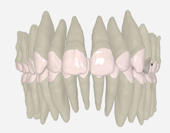
- When there is no CBCT, simulated roots give you an estimated root position based on the long axis of the crow. They won’t show the patient’s real anatomy, so treat them as a prompt to look closer rather than a measurement. Still, they help you judge tooth angulation and spot movements that deserve a second look, which is more than crowns alone can offer.
2. Follow How Teeth Move, Stage by Stage
Movement Table
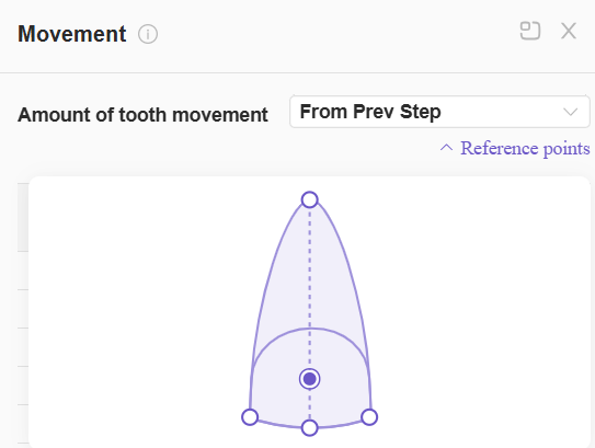
- The final position is only part of the picture. The movement table lists planned movement at every stage, and you can change the reference point between root tip, centre of crown and incisal tip (center or edges) as shown in figure 3. That matters because the same movement reads differently depending on where you measure it. A tooth that looks like a small crown shift can involve a much larger root movement, and the reverse. Switching the reference point lets you see which one you are actually asking the aligners to do.
Staging
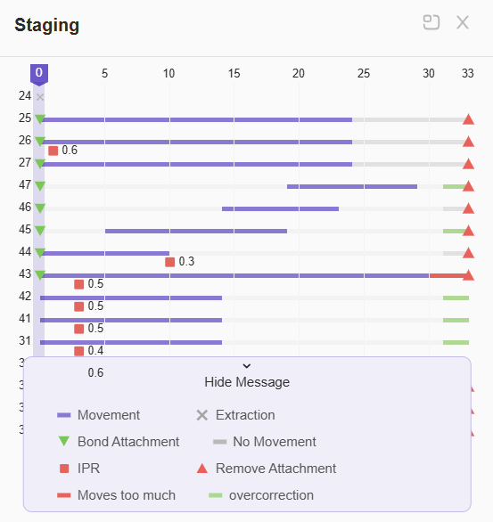
- The staging feature shows which teeth move at which stage along the timeline, as well as attachment placement (green triangle) and removal (inverted red triangle) and IPR sessions (red boxes). Overcorrection steps are shown in green on the timeline. Simulated bite jumps are marked in orange and can now be either incremental or single depending on the amount needed for the case. These bite jumps are not shown on the staging feature, but they are shown on the staging timeline at the bottom.
3. Check the Planned Outcome with Measurements
A visual check is essential, but numbers help you see what the eye can miss.
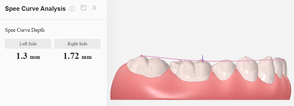
Curve of Spee
- Right and left sides are measured separately at every stage. This shows whether leveling is progressing evenly and how much intrusion or extrusion is built into the plan (4).
Crowding
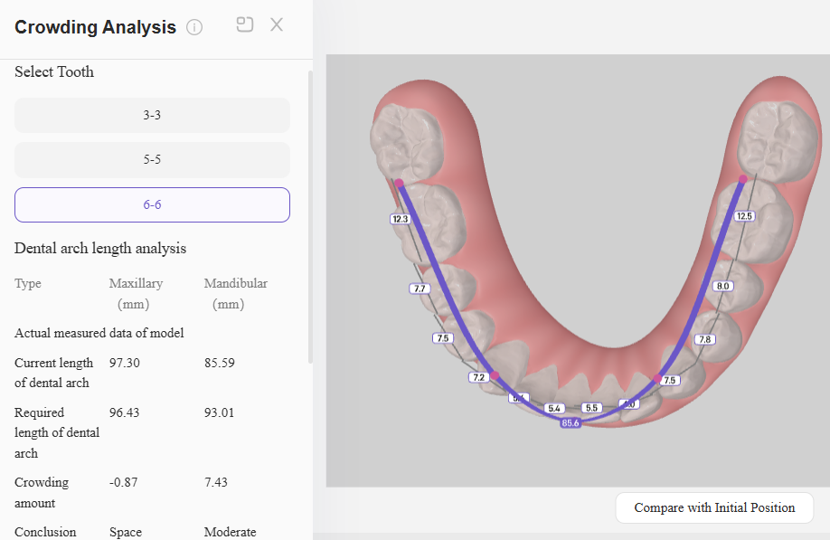
- Measured space discrepancy helps you decide between IPR, expansion and other space-management options. The measurements guide the decision, but the final approach still depends on the individual patient.
Symmetry
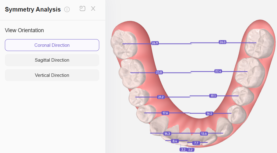
Compares contralateral teeth in all three planes. Viewed coronally, it shows each tooth’s position relative to the midline. Viewed sagittally, it shows whether right and left teeth sit at the same anteroposterior position. Vertically, it shows differences in intrusion or extrusion between the two contralateral teeth.
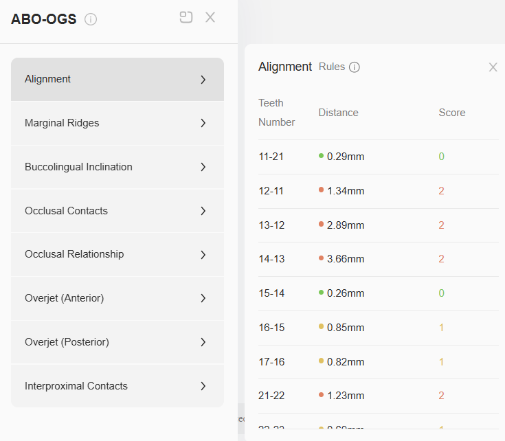
ABO-OGS
A structured review of the planned occlusal result against established objective grading criteria (5). It is a useful reference for judging a setup, not a guarantee of the final outcome.
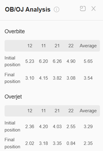
Overbite and Overjet
Initial and final values for each upper and lower central and lateral incisor, so you can see how the anterior relationship is expected to change and compare it with inclination and the rest of the occlusion.
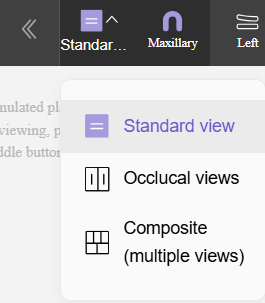
4. Pick the View that Fits Your Question
Standard view shows both arches together, which suits an overall look at the relationship. Occlusal view places the arches side by side, which is better for arch form, symmetry and space distribution. Composite view shows the upper, lower, right, front and left views at once, so you can review without switching. You can step through the stages in all three.
5. Measure and Check Contacts
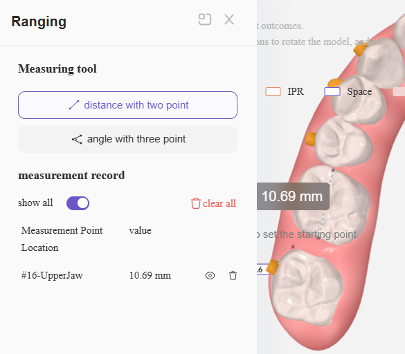
Ranging
- The ranging tool measures distance between two points or an angle between three, for when you want a number instead of an estimate. For example, if you want to reserve an extraction space for a future implant, this can be a helpful tool to utilize.
IPR & Spacing
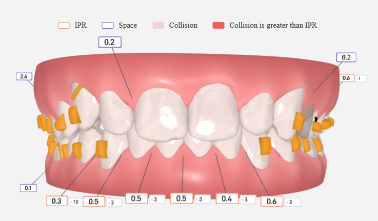
- IPR and spacing values appear directly on the 3D model at each stage, which helps when deciding whether IPR is needed and before which step. IPR shows as a white box with an outer orange lining with the amount of IPR required inside, and with a box next to it at the step before which IPR should be applied. Spacing appears in a white box with a purple outer lining.
In Short
These tools don’t replace clinical judgment. They give you more information at the point where you decide whether a plan is right: where the roots are, how the movement is distributed, and what the bite will look like when it’s done.
FAQS


References
Related Articles

Dental Ergonomics: A Guide to Boost Productivity & Reduce Injuries

Overcoming Common Challenges with Clear Aligners

Eon Aligner Case Gallery: Key Benefits & Case Studies Using Aligners

© Eon Aligner Copyright 2023 All rights reserved


